ELECTROLYSIS PLATES
SELF CLEANING ELECTROLYSIS PLATES
Non Toxic Electrolysis Plate and Methods to Increase Electrolyses Gas Production.
No public disclosure of this invention has been made; (e.g., publication, public use, offer for sale) at any time before the provisional application filing date that would preclude patenting in the United States.
A provisional application provides the means to establish an early effective filing date in a later filed nonprovisional patent application filed under 35 U.S.C. §111(a). It also allows the term "Patent Pending" to be applied in connection with the description of the invention.
APPLICATION FOR US PROVISIONAL PATENT
This application is prepared for a US patent entitled “Non Toxic Electrolysis Plate and Methods to Increase Electrolyses Gas Production,” which is incorporated herein by reference in its entirety.
FIELD OF THE DISCLOSURE
The present invention generally relates to electrolysis, and more particularly, to generating hydrogen and oxygen gasses from water using electric current. The gasses are generally usedas a fuel, either used separately as H2 or H and O, or used as H2 / H and O together (HHO) for engines, turbines, fuel cells, burners, and other devices that burn or use a hydrogen fuel.
The present invention relates to the eliminating the toxic by-products of electrolysis from metallic electrolysis plates and the increasing efficiency of present state of the art electrolysis hydrogen / oxygen gas-from-water generators that use electrolysis to break down H2O into H2 (HH) and O for use as a fuel, either used separately as H2 and O, or used as H2 and O together for engines, turbines, fuel cells, burners, and other devices that burn or use a fuel.
BACKGROUND- PROBLEMS
Electrolysis is the process where an electric current flowing from one conductive surface to another in the presence of an electrolyte conductive liquid will cause a component in the electrolyte to break into its component atomic elements. This is useful in breaking water into hydrogen and oxygen for fuel or other purposes.
The technology of "cracking" H2O into the gasses hydrogen and oxygen for use in internal combustion engines and fuel cells for various other uses has been of great and increasing interest due to the combustion products of H and O being relatively environmentally clean and free of pollutants, CO2,CO or residue and the positive ecological and economic impact of burning less petroleum hydrocarbon fuels. H and O can be compressed and stored in tank(s) either together or separately for use later which is useful when sporadic and unreliable power sources such as solar cells or wind energy are used to provide the electricity for electrolysis.
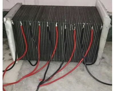
Most hydrogen-oxygen electrolysis generators use metallic or stainless steel electrolysis plates mounted parallel closely together in water mixed with an electrolyte to provide electrical conductivity through the water between the plates, and a DC electrical current applied to the arrangement of parallel, closely spaced electrolysis plates in an alternating positive and negative current plate arrangement, which causes the H2O molecules to release the H and the O in the form of H and O bubbles on the plates which gas rises to the top of the liquid surface and collected above the electrolyte liquid level within the top of the sealed electrolyte and plates case. FIGURE 1a page 14
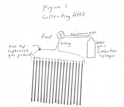
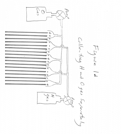
The H and O bubbles are collected in some arrangement above the arrangement of parallel conductive plates, where the H and O gas can be collected together as HHO, FIGURE 1 page 15 or separately as H and O in separate tanks FIGURE 1d page 16. The collected gas(es) are usually used directly when produced, or stored in pressure cylinders for storage for use later. Whether HHO or H and O separately, the gasses are commonly used as a fuel for internal combustion engines, or fuel cells. or for various types of burning and heat production such as boilers, furnaces and ovens. Storage in pressure cylinders is useful when the DC electrical power is supplied by variable and or unreliable or intermittent power sources such as solar cells or wind generators or water power generators (tides, etc) are used to provide the electricity for electrolysis.
During the process of electrolyses, stainless steel and other metallic plates and connectors, hardware and wires, may leach out toxic substances such as CrO5 chromium pentoxide which collect at the bottom of the electrolysis cell as a toxic sludge. Eventually this toxic sludge level in the cell will become high enough to create an electrical connection and a short circuit between oppositely changed electrolysis plates, causing the cell to cease to generate gasses and creating a direct short to the power source. This sludge also collects on the surfaces of the electrolysis plates as a "scum" which diminishes the electrolysis production.
Presently, at intervals, the electrolysis cells must be disassembled to clean the toxic sludge from the bottom of the cell and from the plates, causing costly and inconvenient downtime and interruption of service.
The toxic or non toxic sludge may form a scum on the electrolysis plate surfaces which creates a barrier on the surfaces of the plate that degrades the electrolyses production of gasses from the surface the plates. This toxic or non toxic scum must be removed periodically to maintain a high level of electrolysis gas production.
Collected toxic sludge must be chemically neutralized so the resulting non toxic sludge may be disposed of properly as a non-toxic waste.
The above cleaning and chemical neutralizing process interrupts the production of H and O, causing costly and inconvenient downtime; and the toxic sludge neutralization chemicals are expensive and its proper disposal is costly. The handling of the toxic sludge is hazardous and requires special hazmat clothing, eye protection, etc. which is costly, inconvenient and time consuming and can extend downtime and cause costly insurance issues.
In the present invention, the electrolysis plates are made of a conductive non metallic material such as carbon, which may be pure carbon, carbon fiber sheets or some other form of carbon. This may include carbon impregnated plate materials or carbon coated or carbon clad conductive materials on conductive or non-conductive metallic or non metallic substrates. Conductive materials other than carbon may be used.
The plates may also be made of a metallic material with generates no toxic sludge.
Corrosion on the surface of electrolysis plate materials will diminish gas production due to the insulating properties of corrosion. The present invention uses any electrolysis plate materials that will not corrode.
When used in electrolysis, carbon plates and other non toxic generating plate materials discussed above, do not create any by-products or sludge. As carbon is inexpensive, there are cell acquisition cost savings and from the absence of toxic sludge, considerable operating expense savings in the electrolysis production of the H and O gasses.
The carbon plates are lighter than metal, resulting in a lighter electrolysis cell; important in vehicle applications.
It is noted that impurities in water (when steam distilled water is not used) will contaminate the electrolysis surfaces of both metal and carbon plates which may need to be cleaned to provide clean surfaces for maximum electrolyses effect. Steam distilled water contains no contaminants to degrade H and O production from electrolysis.
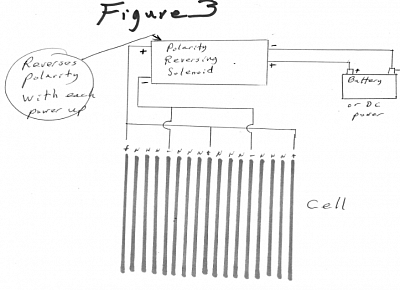
The present invention may include an electrical polarity reversing device that will reverse the direct current electrical polarity to the plates periodically, either automatically or manually on command; reversing the plate polarity will cause negatively particles / contaminants that are adhered to the positive current plate to be repelled when the current polarity to the plate is reversed to negative; positively charge particles/contaminants will be repelled from the surface of the negatively charged plate when the plate is switched to a positive charge because like charged particles repel each other. In this way the plates can be partially cleaned for greater gas production with no down time and no mechanical intervention. FIGURE 3 page 17
When HHO is desired to be collected; reversing the current to the plates will have no effect on Hydrogen and Oxygen gas collection other than increasing gas production as the plates are partially cleaned through the reverse charge effect FIGURE 1.
If it is desired to collect Hydrogen and Oxygen separately, whenthe electrolysis current polarity is reversed, valves in the gas vent tubing from the electrolysis cell to their respective gas collection chambers will operate manually or automatically to divert the Hydrogen and Oxygen separately to their respective separate H and O collection chambers separately FIGURE 1d page 16.
Carbon plates may be coated with a conductive coating which may be non stick to minimize electrolysis plates becoming coating with residue which may diminish gas production.
A small amount (1% to 10% of the total electrolyte) of ethyl or pentanol or octonol or other alcohol may be added to the electrolyte chemicals as a fluid surface tension reducer / breaker to increase efficiency of the cell by making the gas bubbles smaller and to make the bubbles release quicker from the plates - increasing production volume of Hydrogen and of Oxygen at the same watts of power due to more actual area of plates in direct in contact with the electrolyte instead of in contact with gas bubbles.
Since electrolysis gas production degrades as the electrolyte heats up, the invention reveals that by using a low voltage DC current for electrolysis will cause lesser heating of the electrolyte; keeping it cooler and much more efficient. The most efficient voltage for plate type electrolysis gas generators is between 1.6 and 1.8 volts DC, un-modulated; uninterrupted flat wave DC current. The actual most efficient voltage must be determined experimentally for each configuration and material of electrode and electrolyte and the electrolyte type and concentration.
In order to use such low voltages, the electrolyte must be of higher concentration to allow necessary current to flow between the plate electrodes. Concentrations of electrolyte in the water of between 25% and 40% or higher will provide optimum gas output at the low voltage as seen above.
With higher concentrations of electrolyte, the electrolyte may become thick and not flow well between the plates. Adding a surface tension breaker such as ethyl or pentanol or octonol or other alcohol or other surface tension reducing chemical will lower the electrolyte viscosity, allowing it to flow better between the plates.
A surface tension reducing chemical such as an alcohol such as ethyl or pentanol or octanol is used to cause the gas bubbles to release from the electrode (plate) very quickly thus increasing the total surface area of electrodes that are in contact with the electrolyte. Alcohols are unusually compatible and effective with KOH and other electrolytes. Light alcohols like ethyl boil off quickly and have to be replenished often, heavier alcohols like pentanol or octonol will last longer in the warm or hot, roiling electrolyte during gas generation. Exact concentrations of alcohol are determined experimentally in each unique electrolysis gas generator configuration, but generally he amount of an alcohol will be 1.8 to 10% or higher of the total electrolyte volume. The gas generator operator should test for alcohol concentration regularly during operations to replenish alcohol that flashes off as a gas.
In the electrolysis process, any sharp edge on charged materials will leak current into the electrolyte and therefore reduce the efficiency (gas production per Watt of power). Electrode plate edge efficiency losses can be minimized by rounding or covering all sharp edges with an insulating material. Sharp plate edges in plate type generators can be covered with any insulating material that will not be removed by the electrolyte and will not contaminate the electrolyte. Such insulator may be painted; sprayed, bonded, taped or applied in any manner necessary.
Edge loss effect can be used to advantage to increase the efficiency of the generator by creating “edges” on the surface of the electrode plates by rough grit blasting, grinding, sanding, plasma sputtering, plating, etching and any other method that will give the electrolysis electrode plate a rough surface where the surface has a multitude of sharp edges to that will take advantage of the edge loss to increase the flow of current between electrode whose surfaces have been roughed up to create surfaces that have a multitude of “edges”. Electrode plates can have a rough surface and additionally the surface can be fabricated similar to surface of a golf ball's dimples, where the plate has numerous very small sharp edge "craters" in the plate where the crater edges will have the sharp edge effect of increasing current flow between the plates and therefore, increased gas production The generator can be made to be self-filling from a separate reservoir of water and de-foaming alcohol FIGURE 8 page 19to eliminate the need to manually fill the generator container often; when the generator is turned off the process of cooling electrolyte causes a partial vacuum to form in the generator vessel; a tube from the generator vessel to the water / alcohol reservoir will cause fluid from the reservoir to flow from the reservoir into the generator vessel to replace water / alcohol that have been consumed in the generation process. The tube inlet into the electrolyses cell is positioned so the cell will not overfill. The refilling from the reservoir eliminates the maintenance requirement of continually refilling the generator when fluids are consumed.
Additionally, a tube can be run from the device used to separate the electrolyte from the gas (the “bubbler”) to be drawn by the vacuum into the generator vessel to continually “empty” the bubbler device eliminating this maintenance requirement. Check valves are used to allow the captured fluids from the bubbler to flow only into the fluid reservoir. The cell container may have a removable plug in its bottom that will facilitate emptying out any sludge in the bottom of the cell, or to change out or drain out some of the electrolyte or flushing the cell out to purge or clean it. The bubbler container and / or the fluid reservoir may have a removable plug in its bottom that will facilitate emptying out any excess electrolyte.
CLAIMS - SOLUTIONS
In the present invention, the electrolysis plates are made of carbon which may be carbon fiber sheets or some other form of carbon. This may include carbon impregnated plate materials or carbon coated or clad conductive or non conductive substrates. When used in electrolysis, carbon plates do no create any toxic or non toxic byproducts or sludge. As carbon is inexpensive, there are cell acquisition cost savings and considerable savings in due to the reduction / absence of the sludge, the increased electrolysis production of the H and O gasses.
To keep the electrolysis plates clean of residue buildup, the present invention includes an electrical polarity reversing device Figure 3, that will reverse the electrical polarity of the electric power to the plates on command; reversing the plate polarity will cause positive charged particles that are adhered to the negative current plate to be repelled away when the current to the plate is reversed to positive; positively charge particles will be repelled from the surface of a plate when it has a positive charge. In this way the plates may be cleaned with no down time and no mechanical intervention.
When HHO is desired to be collected; periodically reversing the current polarity to the plates will have no effect on Hydrogen and Oxygen gas collection. If it is desired to collect Hydrogen and Oxygen separately, valves in the gas venting tubing from the electrolysis cell to their respective gas collection chambers will manually or automatically close and opened to divert the Hydrogen and Oxygen separately to their respective separate H and O collection chambers / pressure vessels. Figure 1d
Carbon plates may be coated with a conductive non stick coating to minimize plates becoming coating with electrolyte residue and other electrolyte residue.
Since electrolysis gas production degrades as the electrolyte heats up, the invention reveals that by using a low voltage DC current for electrolysis will cause reduced heating of the electrolyte; keeping the electrolyte cooler and more efficient. The most efficient voltage for plate type electrolysis gas generators is between 1.6 and 1.8 volts DC, un-modulated; uninterrupted DC flat wave. The actual most efficient voltage must be determined experimentally for each configuration and material of electrode and electrolyte and the electrolyte type and concentration.
In order to use such low voltages, the electrolyte must be of high concentration to allow a low current to flow between the electrodes. Concentrations of electrolyte and water of between 25% and 40% or higher will provide optimum gas output at the low voltage as seen above.
Surface tension reducing chemicals such as an alcohol, as ethyl or pentanol or octanol and other suitable Surface tension reducing chemicals is used to cause the gas bubbles to be smaller and to release from the electrode (plate) more quickly thus increasing the total surface area of electrodes that are in contact with the liquid electrolyte and reducing the plate surface in contact with gas bubbles. Alcohols are unusually compatible and effective with KOH and other electrolytes. Light alcohols like ethyl boil off quickly and have to be replenished often, heavier alcohols like pentanol or octonol will last longer in the warm / hot roiling electrolyte during gas generation. Exact concentrations of the Surface tension reducing chemicals are determined experimentally in each unique generator configuration, but generally the amount of an alcohol will be 1.8 to 10% of the total electrolyte volume or higher. The gas generator operator should test for alcohol concentration regularly during operations to replace alcohol that flashes off as a gas. Alcohol may be added to the electrolyte chemicals to increase efficiency of the cell to make the gas bubbles smaller and release quicker from the plates thus increasing production volume of Hydrogen and of Oxygen at the same watts of power.
Electrode Edge efficiency losses can be minimized by covering all sharp edges with an insulating material. Sharp plate and conductor edges in plate-type generators can be covered with any insulating material that will not be removed by the electrolyte and will not contaminate the electrolyte. Such insulator may be painted; sprayed, bonded, taped, clad or applied in any manner necessary.
In electrolysis the current collects on edges and points of the conductive surfaces and the electric current flows from these edges and points at a higher rate than the flow between flat areas of the conductor plates. Electrical flow from edges and sharp surfaces diminishes the efficiency of the system due to the fact that the conductor surface area at these edges and points is small and the surface area of the conductor plate is the gas generation surface. The larger the surface of the conductor at a given charge, the more gas is produced. Electrical flow from edges and points creates little gas at the small surface area of the edge or point compared to the large area of the main part of the conductor where surfaces are essentially “flat” and not edges or points.
Edge loss efficiency loss can be minimized by applying an electrical insulator or electrical insulation coating to the edges and sharp points of the sharp edges, pointed surfaces of the plates, wires, brackets and connectors in the electrolysis cell. Such insulation may be mechanically applied, painted, plated, clad, bonded or chemically applied or fused to the sharp surfaces and edges of the conductive plate.
This edge effect can be used to advantage to increase the flow of current between conductive surfaces by roughing up smooth conductor surfaces into a very large number of very small sharp edges on the conductor surfaces. In this way the flow of current between conductive plates is increased by making the surface of each surface a very large field of sharp points and edges down to a microscopic scale.
Conductor surfaces can be roughed up into many tiny sharp edges by grit blasting, chemical etching, mechanical machining, sanding, grinding, stamping, and any other method available to create many sharp edges on conductor surfaces. In this way current flow to the conductor surfaces is increased due to the “edge losses effect” - current flow between sharp surfaces of one conductor onto the sharp surfaces of the conductor of opposite charge.
Sharp electrode and electrode support edges may be rounded off or smoothed during plate and plate support fabrication; eliminating sharp edges and their associated losses.
Additionally the electrode plate surface can be fabricated like the surface of a golf ball's dimples, where the plate has numerous sharp edge "craters" in the plate where the crater edges will have the sharp edge effect of increasing current flow between the plates and therefore, increased gas production.
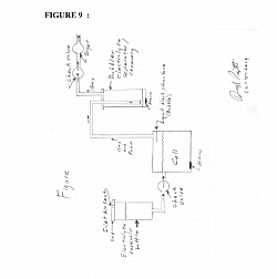
The generator can be made to be self-filling Figure 8from a separate reservoir of water and de-foaming alcohol , Surface tension reducing chemical to eliminate the need to manually replenish the generator container with (distilled)water and alcohol often; when the generator is turned off the process of cooling electrolyte causes a partial vacuum to form in the generator vessel; a tube from the generator vessel to the water / alcohol reservoir will cause fluid from the reservoir to flow from the reservoir into the generator vessel to replace water / alcohol that have been consumed in the generation process. This eliminates the maintenance requirement of continually refilling the generator when fluids are consumed. A check valve may be used to prevent flow from the cell to the reservoir.
The electrolysis cell body may have heat sinks, heat exchanger or other methods for cooling the electrolyte, such cooling may be air or liquid cooling. The electrolysis cell body may be air cooled and may have a fan blowing over its surface or heat sink fins for cooling the electrolyte. The electrolysis cell body may liquid cooled by heat exchanger to transfer the heat from the cell electrolyte to a colder medium.
The gas output tube from the cell can be run from the generator cell to a separate container where any electrolyte in the cells vent gas tube is separated from the gas. Figure 8.The “bubbler” will trap any electrolyte that flows out of the gas vent tube. The trapped electrolyte at the bottomed of the bubbler container will be drawn by the vacuum caused as the cell cools into the generator vessel when the electrrolyte cools after use to continually “empty” the bubbler device eliminating this maintenance requirement. Check valves are used to allow the fluids from the fluid reservoir and or bubbler to flow only into the generator vessel and no gas to flow from the generator vessel to the fluid reservoir or the bubbler. FIGURE 8
The cell may have a removable plug in its bottom that will facilitate emptying and rinsing out any sludge in the bottom of the cell, or to change out or drain out some of the electrolyte or flushing the cell out to purge or clean it. FIGURE 8
The electrolysis cell may be constructed with two orthree or more neutral electrode plates between each pair of charged electrodes to increase gas production. These neutral plates may be connected to a ground / earth ground and not to positive or negative DC electricity.
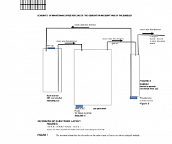
The invention claims that the electrolysis cell is so constructed the electrodes on the ends of any cell array are always charged similarly to increase gas production FIGURE 1, 1d, 3, 6,
The invention may include a threaded / unthreaded plug at the bottom of the bubbler, fluid reservoir and electrolysis to remove excess electrolyte or fluids, for rinsing and cleaning. FIGURE 8
The invention may pulse the DC power to the electrolysis plates. From 1 CPS to 240 CPS to increase gas production; the pulsing may be at timed or random intervals between current flow; maximum effect will depend upon many variables including voltage, amperage, electrolyte solution, plate geometry, temperature and many other variables.
The invention may alternate polarity of the DC power to the electrolysis plates to increase gas production. From 1 CPS to 240 CPS, the pulsing may be at timed or random intervals between current flow; maximum effect will depend upon many variables including voltage, amperage, electrolyte solution, plate geometry, temperature and many other variables.
The invention may both pulse and alternate polarityat the same time; in any sequence of cycles whether varying or not variable, random or timed.
BRIEF DESCRIPTION OF THE DRAWINGS
FIGURE 1a:
shows a typical electrolysis cell with its electrolysis plates and electrolyte fluid between the plates with gas venting into tubes on top of the cell.
FIGURE 1d:
gas collected separately as H and O: shows valves in the gas tubing flowing from the electrolysis cells to their respective gas collection containers. Valves manually or automatically close and opened to divert the Hydrogen and Oxygen gasses separately to their respective exclusive collection containers depending upon the polarity of the current sent to each plate.
Figure 3:
showing the reversing of electrical polarity to the electrolysis plates. Reversing device may also include pulsing circuitry.
Figures 8 & 9:
Showing a separate water and alcohol reservoir container that automatically keeps the cell electrolyte at full level. Electrolyte is separated from the gas.[0055] Figure 8, 9 The invention claims that a plug at the bottom of the bubbler, reservoir and cell for access to remove excess electrolyte.

